Juan Bernardo Pastuszak
All projects

Team SLowMo · UKSEDS Satellite Design Competition · 2024 to 2025

CubeSat Vision and Attitude Control

Developing and testing a camera-guided payload for the UKSEDS Satellite Design Competition

Team SLowMo built a CubeSat demonstrator to show how existing computer vision techniques could support target tracking for satellite docking. I integrated established vision libraries with the camera, ground software and reaction wheel control to turn the suspended demonstrator towards a marked target.

My contribution

I developed the payload system: camera processing, ground station interface and Raspberry Pi control software. I selected the motor, designed the reaction wheel, built test rigs and operated the demonstrator at the national final.

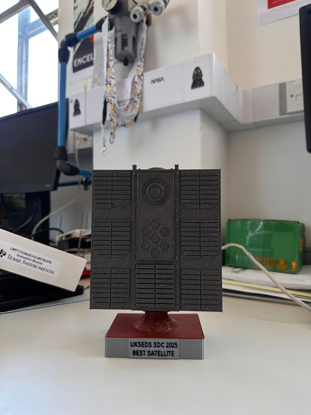
Team award: Best Satellite

The assembled demonstrator rotating during ground testing. Select the video to play it.

Results from the demonstrator tests

Camera distance checks
±1 mmCamera distance accuracy in my checks against manually measured reference distances.
LiDAR distance checks
±3 cmLiDAR distance accuracy in the same reference-distance checks.
Reaction wheel revision
Vibration resolvedThe acrylic wheel and rim bolts resolved the vibration observed with the original aluminium wheel.
My first prototype: a printed AprilTag tracked through the laptop webcam, before the satellite’s own camera was used. Select the video to play it.
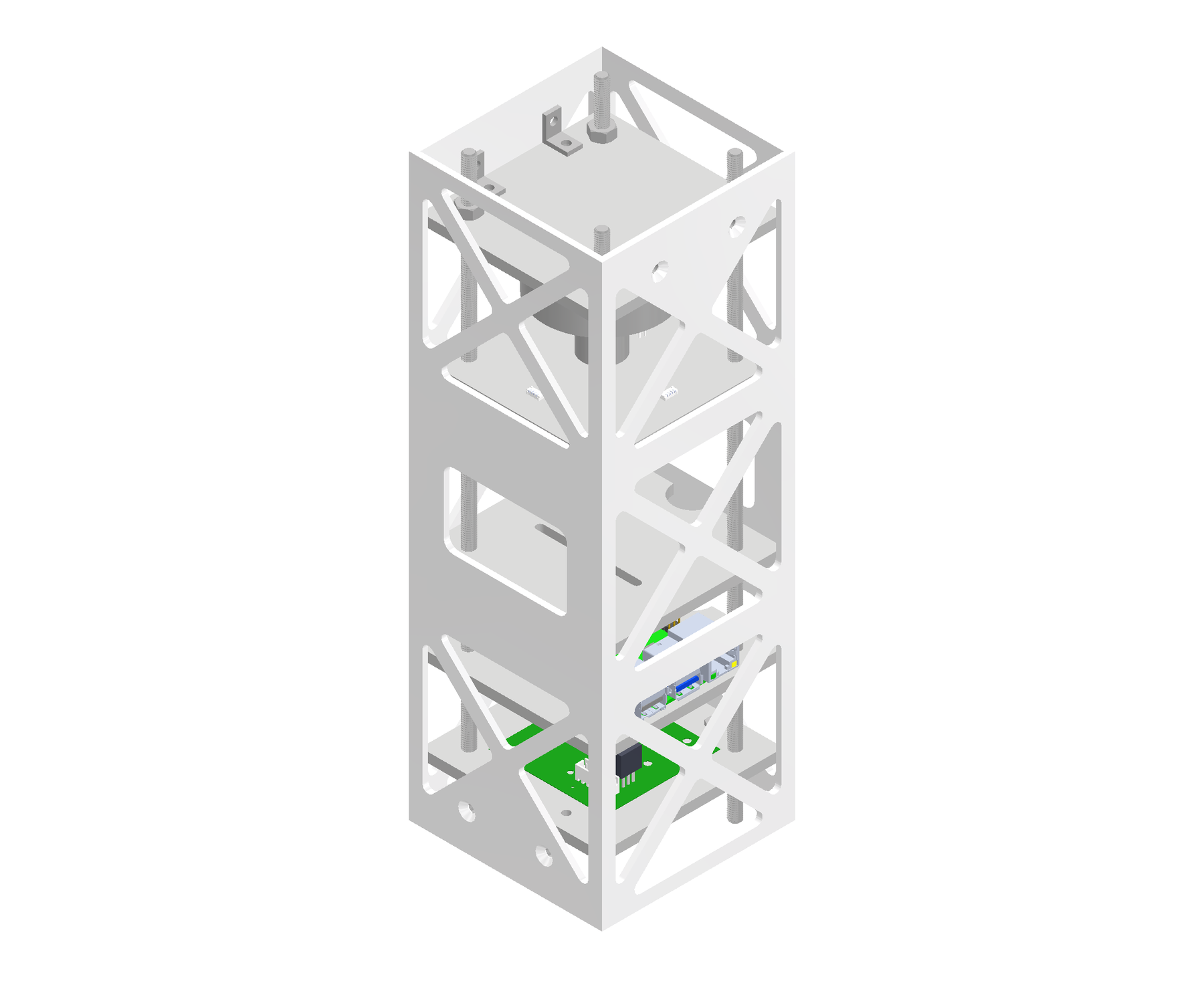
Saved team CAD assembly showing the CubeSat structure and internal equipment
Team CAD showing the structure and internal equipment layout at an earlier design stage. Some components differ from the final hardware.

Tracking the Target

Integrating camera measurements with the pointing system using OpenCV and AprilTag

Using OpenCV and an AprilTag library, I developed the processing pipeline and connected its measurements to the control system. A fiducial marker of known size let the camera estimate the target’s relative position and orientation, which we used to turn the demonstrator towards it.

I chose a Raspberry Pi 4 and Camera Module 3 for their capability and compatibility. Before the hardware was ready, I developed the Python software with a printed AprilTag and my laptop webcam.

The detector located the marker’s four corners; with its dimensions and the camera calibration, pose estimation gave distance and angle. I drew a 3D outline over the image to see how the estimate followed the target, and added live plots that became the ground station interface. In the hardware version, the Pi streamed images to the ground computer and the angular error was sent back to the controller to drive it towards zero.
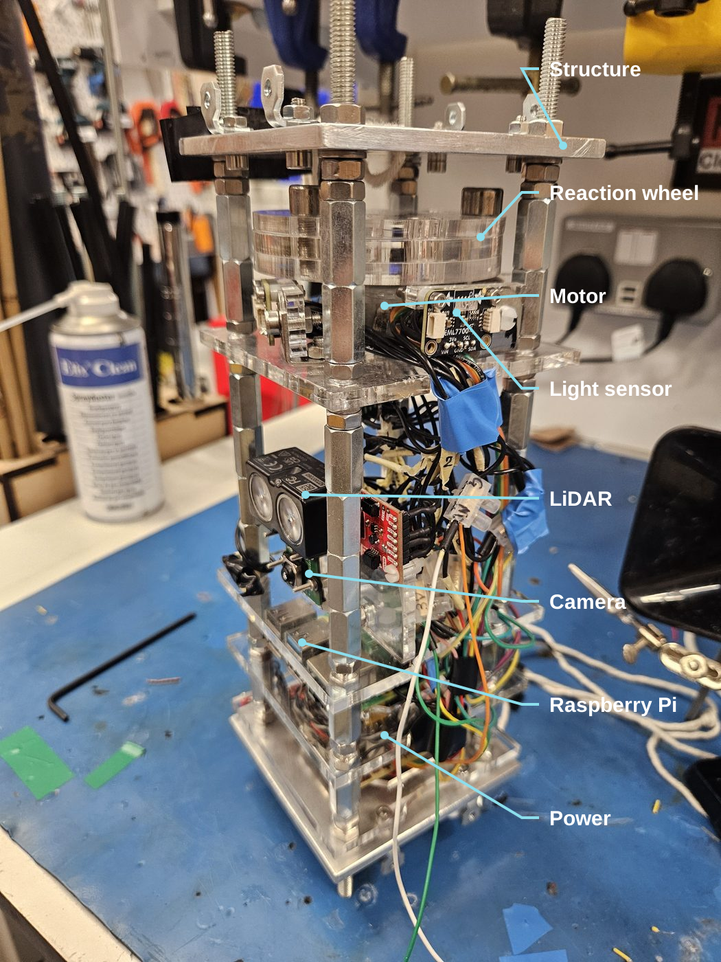
The demonstrator stack with labels for the metal structure, acrylic reaction wheel, reaction-wheel motor, light sensor, Garmin LIDAR-Lite v4, camera, Raspberry Pi 4 and battery and power compartment
The assembled demonstrator, labelled. The acrylic reaction wheel carries bolts around its rim.

Designing the Reaction Wheel

Sizing the wheel, investigating vibration and improving the hardware

I designed the reaction wheel and integrated a DC motor, an MP6550 motor driver and an MPU6050 IMU with the control software. Accelerating the wheel turned the suspended structure the opposite way.

The first wheel, a solid aluminium cylinder, vibrated heavily: the motor shaft did not extend far enough through the long wheel to support it, and the test readiness review recorded the motor struggling near its torque limit.

With no time for another machined part, I redesigned it from laser cut acrylic sheets with bolts around the rim. Moving mass outwards kept useful inertia with less total mass, and the new wheel resolved the vibration problem.

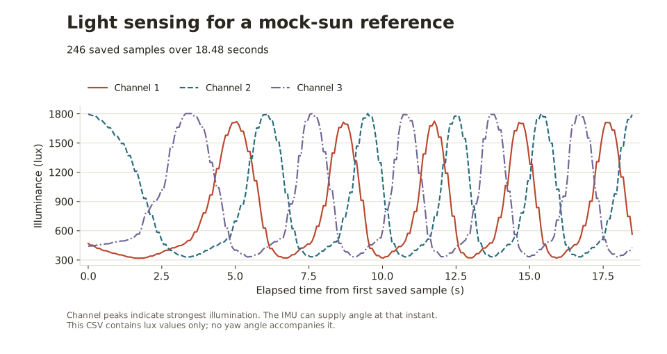
Three light-sensor channels over 18.5 seconds with offset, repeating peaks
Three light-sensor channels recorded over 18.5 s. Each peak marks a sensor facing the lamp.

Keeping Track of Orientation

Combining gyro measurements with a continuous light-based heading reference

To keep track of heading, I combined the gyro with an external light reference that corrected drift and supported searches when the target was out of view.

Three light sensors spaced 120° apart faced a lamp representing the Sun; a peak in each reading marked a sensor facing it. I combined the light and IMU data in Python to update the gyro’s heading, and compared the time between peaks with the measured rotation rate as a check while moving.

If the target was lost, the software returned to its last known direction or swept a full rotation, then switched back to target pointing once the camera found it.

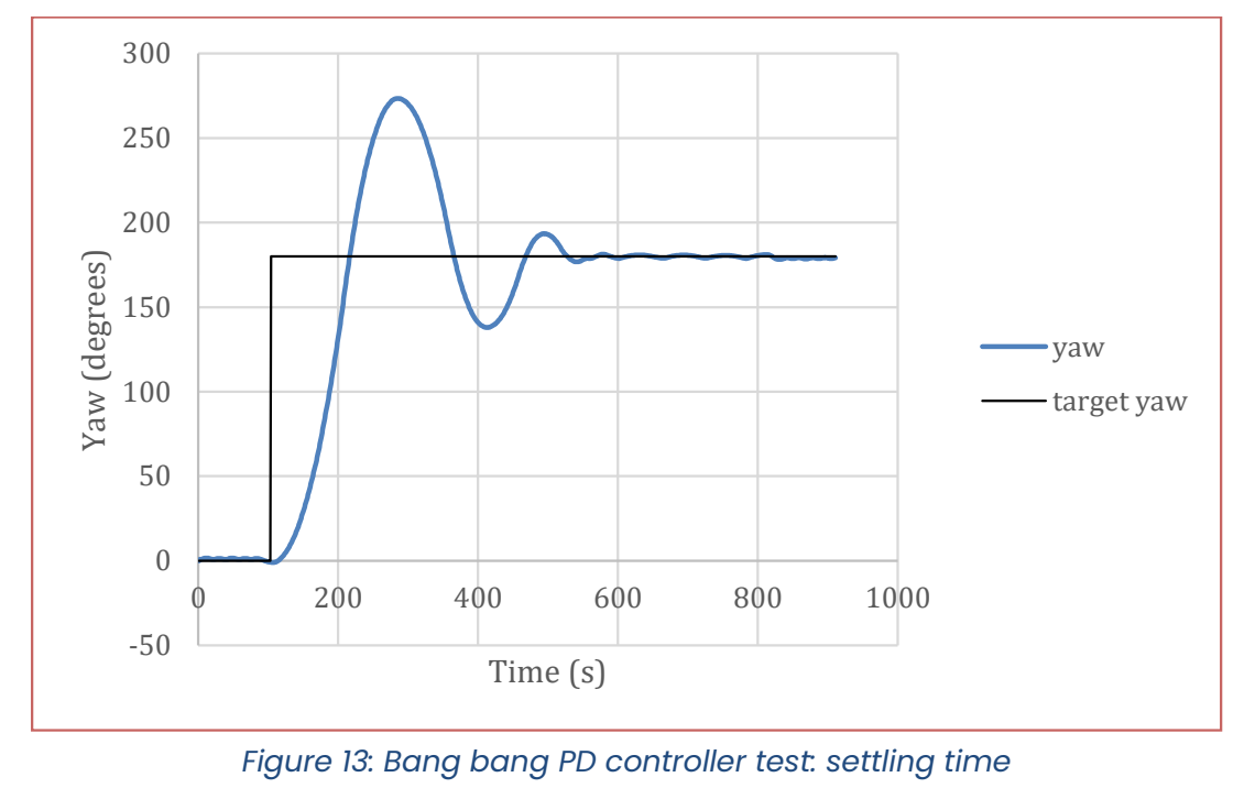
Yaw response overshooting and converging to a 180-degree target
The team’s earlier recorded response to a 180° command, from the test readiness review (labelled bang bang PD), before the PWM and PID changes.

Improving Pointing Control

Moving from full-power switching to PWM and PID control

Our first bang bang controller switched the motor between full drive in either direction, and a 180° command overshot badly. I changed the control software to pulse width modulation through the motor driver, giving the controller a variable input, then implemented PID control and tuned it on the demonstrator. The plot shows the team’s earlier recorded response, before this change.

A disturbance test on the suspended demonstrator. Select the video to play it.

Tuning the Controller on Hardware

Testing pointing response and recovery from disturbances

My simple MATLAB/Simulink model did not capture enough of the real behaviour, so I tuned the controller on the hardware, testing after each change and using the gyro readings to judge overshoot and settling.

I prioritised accurate pointing without overshoot over speed, disturbed the structure by hand to check recovery, and recorded the final settings for reuse.

The moving-marker test cart I built to exercise the camera pipeline. Select the video to play it.

Testing the Payload’s Measurements

Building a moving-target rig and comparing sensor readings with known distances

I wanted to know how accurate the camera and LiDAR readings were, so I tested them against known distances.

I built a four wheeled cart carrying an AprilTag, driven from a web page on my laptop. Against manually measured distances, repeated camera readings were accurate to ±1 mm and LiDAR readings to ±3 cm, worse than its specification suggested, possibly because of surface reflectivity.

Wheel wobble made a steady reference speed hard to hold, so I used the moving runs to assess tracking qualitatively.

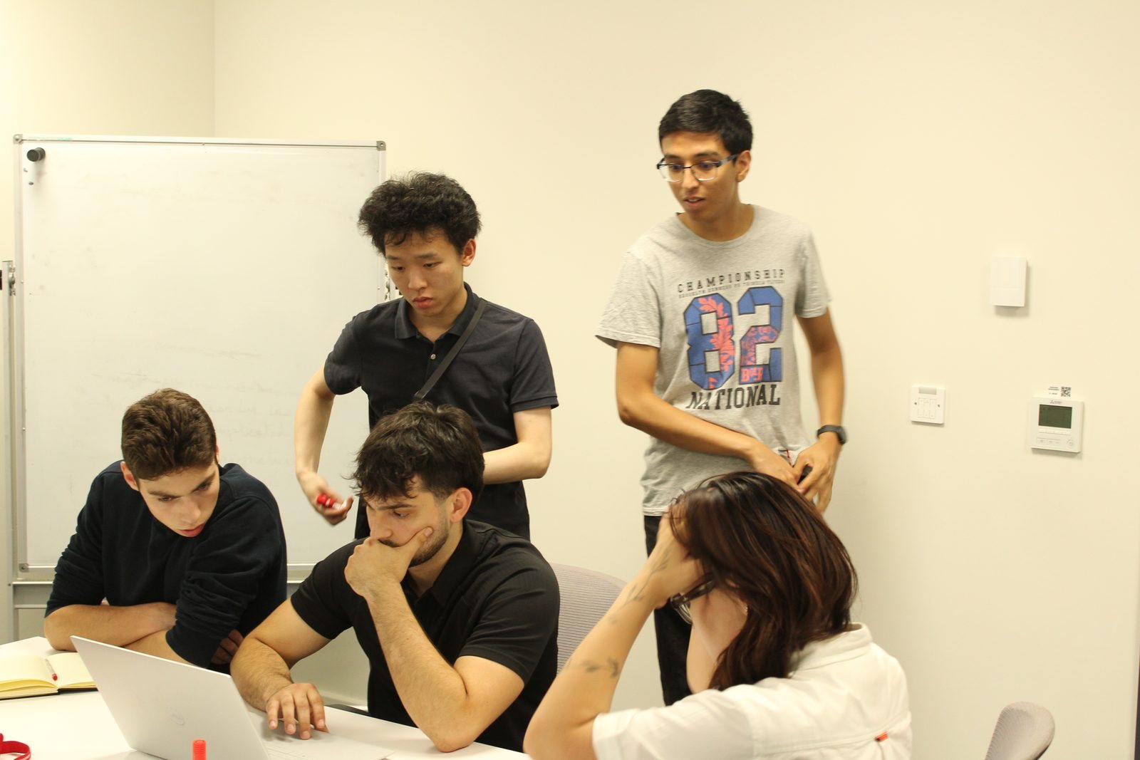
Team SLowMo around a laptop running the ground interface; Juan is seated with his hand on his chin
Operating the demonstrator from the ground interface. I am seated, hand on chin.

Operating at the National Final

Running the ground interface and presenting the demonstrator at Airbus Stevenage

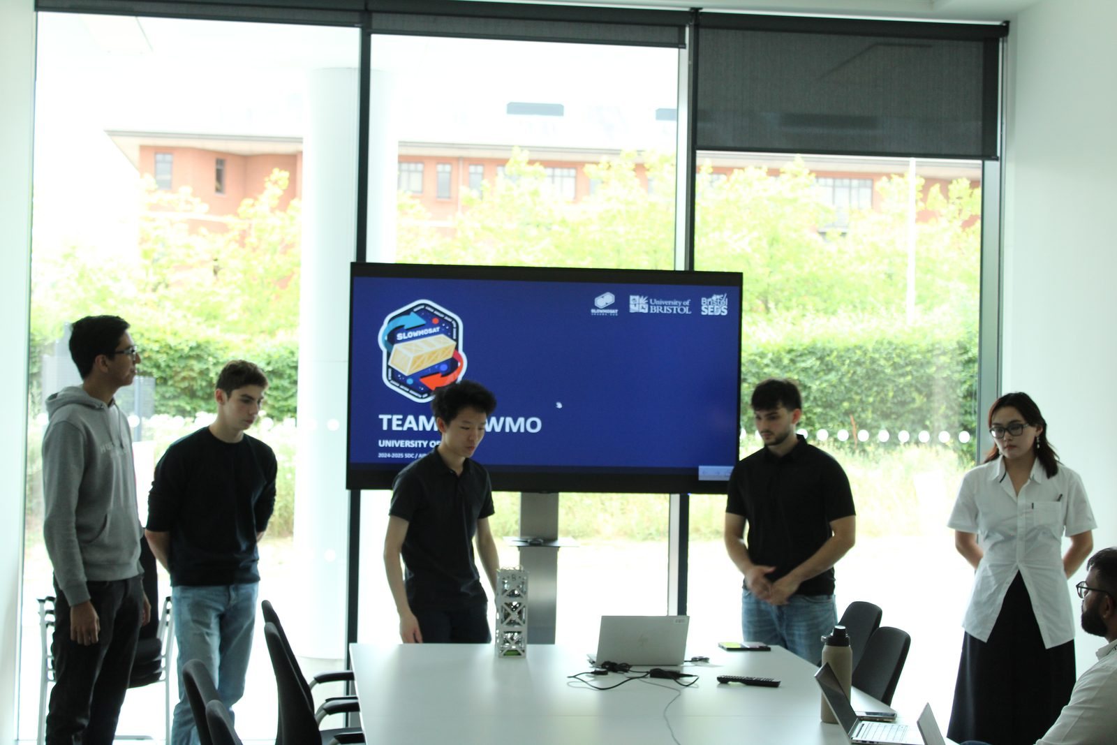
At the national final at Airbus Stevenage in July 2025, I led the mission operation from the ground interface I had built while the team monitored telemetry and the camera feed. We presented and defended the design, and Team SLowMo won Best Satellite.

What I learned from the satellite project

What the project taught me, how the team worked and mentoring the next one

I built systems around existing libraries and checked them with physical tests. The wheel vibration, the controller tuning and the measurement cart each showed me a problem that the code alone would not.

It also depended on the team: my payload needed my teammates’ structural interfaces and power supply, so progress meant agreeing what each part needed and helping beyond our own tasks. What I enjoyed most was seeing our separate contributions become a system we could operate together.

The following year I was technical lead and mentor for Bristol’s next team, helping them through problems I had once found unfamiliar, all the way to the final at Airbus Stevenage.

Team SLowMo presenting the CubeSat demonstrator to judges at Airbus Stevenage
Presenting the demonstrator as a team at the national final, Airbus Stevenage, July 2025.
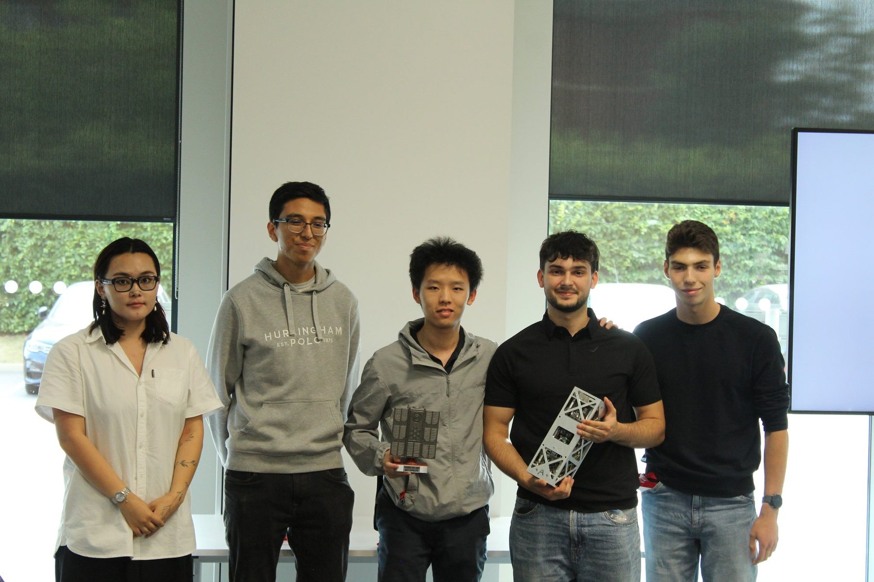
Five members of Team SLowMo with the Best Satellite trophy; Juan holds the satellite structure
Team SLowMo with the Best Satellite trophy, July 2025.
Close-up of the UKSEDS SDC 2025 Best Satellite trophy
UKSEDS Satellite Design Competition 2025: Best Satellite team award.

Tools and methods

Python, OpenCV, MATLAB/Simulink, computer vision, embedded programming, feedback control, CAD and experimental testing