Juan Bernardo Pastuszak
All projects

University of Bristol · Flight Dynamics and Advanced Control project and control design extension · 2025 to 2026

Gain scheduled pitch rate control for a nonlinear F-16 model

Using a supplied nonlinear F-16 model, I investigated longitudinal stability and designed a pitch rate controller. When the gains tuned at 220 m/s lost damping at lower speed, I extended the design to an airspeed scheduled PI controller and tested it across 100 to 220 m/s and in a simulated flight with gusts and sensor noise.

My contribution

I wrote the mode tracking and PI gain search code, built the gain schedule in Simulink and automated the nonlinear comparisons. I also studied actuator rate limits and anti-windup on a linearised model.

Completed simulation study

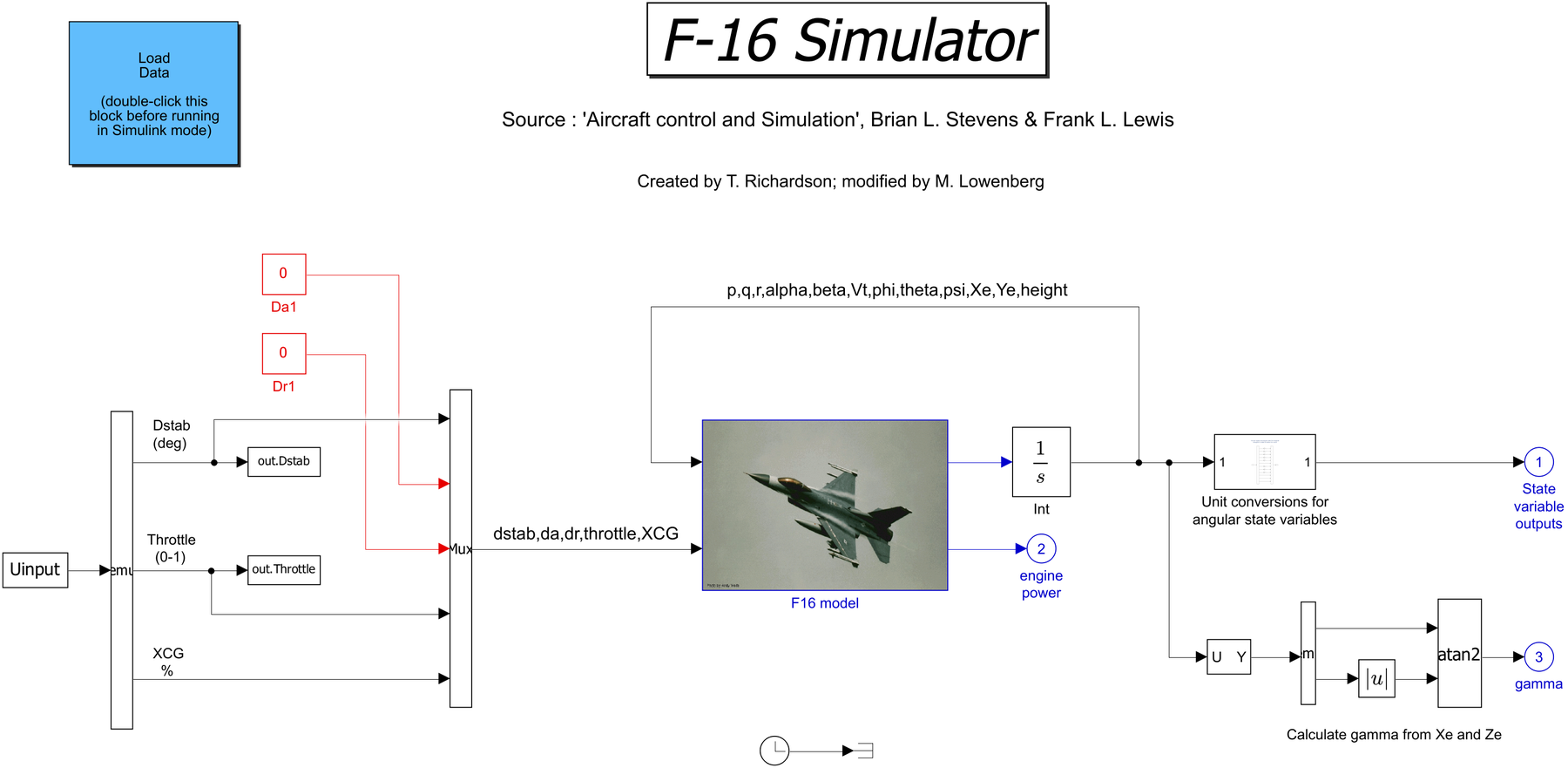
Complete nonlinear F-16 Simulink aircraft model with inputs, state integration and outputs
The supplied nonlinear F-16 aircraft model, with its inputs, state integration and outputs. Direct Simulink export without the controller loop.

Results in nonlinear simulation

Overall disturbed tracking
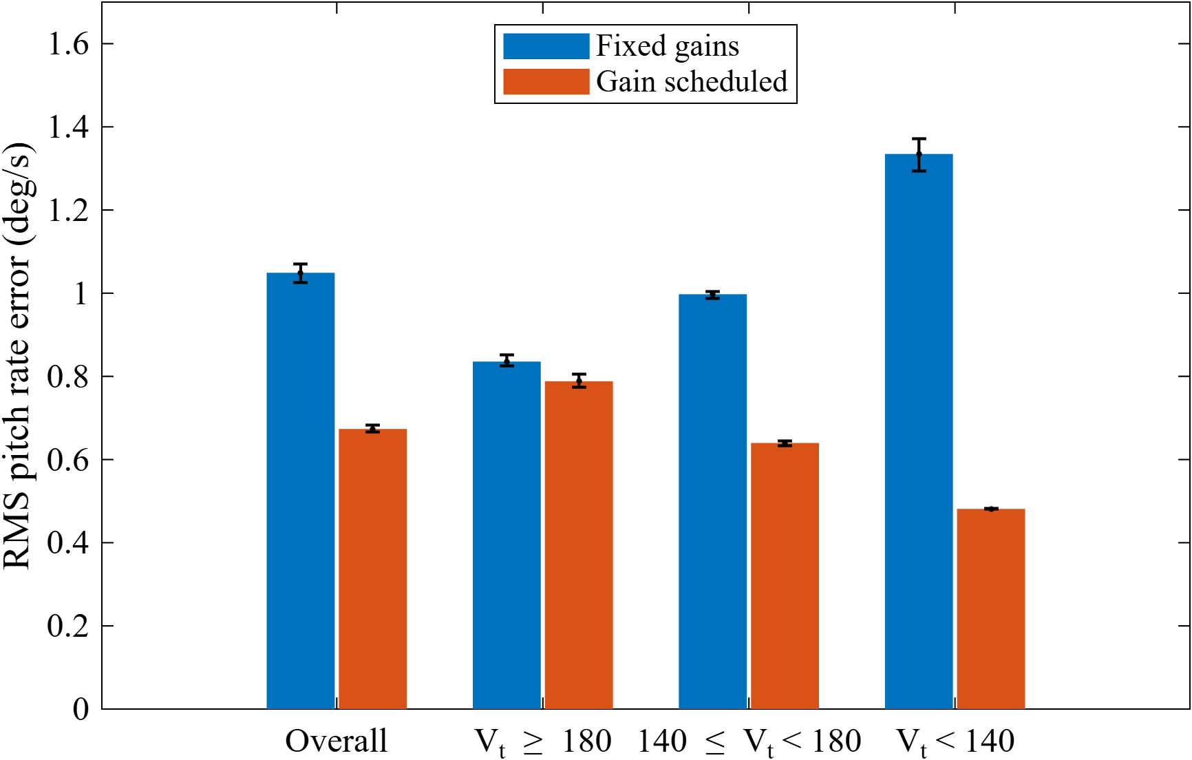
36% lower RMS error1.05 to 0.67 deg/s, averaged over three matched 210 s runs with gusts and sensor noise.
Tracking below 140 m/s
64% lower RMS error1.33 to 0.48 deg/s in the low speed portions of those simulated runs.
Nonlinear step tests
Overshoot below 20%At all 13 tested initial speeds from 100 to 220 m/s. These tests used an ideal stabilator.
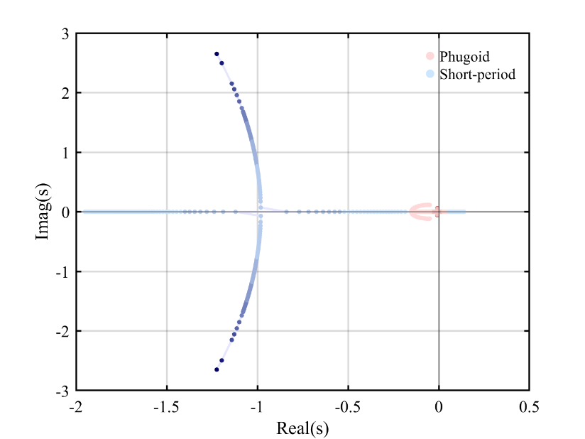
F-16 longitudinal eigenvalue trajectories as the centre of gravity moves aft
Longitudinal pole trajectories across the centre-of-gravity sweep (p. 15).

How moving the centre of gravity changes the F-16 modes

I wrote code to sweep the centre of gravity from 25% to 35% of mean aerodynamic chord at 220 m/s and 15,000 ft, trimming and linearising the aircraft at each position.

Tracking the longitudinal eigenvalues, damping and natural frequency showed the modes approaching the real axis and the aircraft becoming unstable as the centre of gravity moved aft. Where converging frequencies made automatic classification ambiguous, I checked the tracking manually.
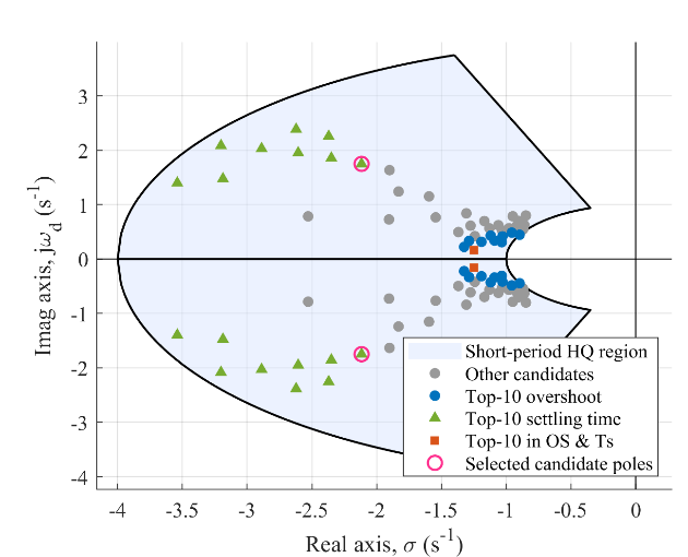
Admissible F-16 closed-loop poles plotted against the short-period design region
Accepted gain pairs and their short-period poles, with transient-performance candidates highlighted (p. 17).

Selecting gains against modal and transient criteria

At 35% mean aerodynamic chord, I extracted a longitudinal state space model with stabilator deflection as the input and pitch rate as the output.

My first attempt used a second order approximation, but the responses were unsatisfactory. I then wrote a MATLAB loop to search PI gain combinations. It rejected unstable designs, checked the short period poles against the coursework’s MIL-F-8785C Level 1 bounds, and measured overshoot, rise time and settling time from the full step response.

I selected Kp = −0.2595 and Ki = −0.7055 from the admissible set. The search shaped the short period mode explicitly and required the phugoid to remain stable.

Pitch-rate step responses at 220 and 100 metres per second against a 5 degree per second demand
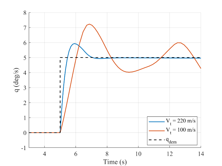
Pitch-rate response to a 5°/s step at 220 m/s and 100 m/s with the same gains.
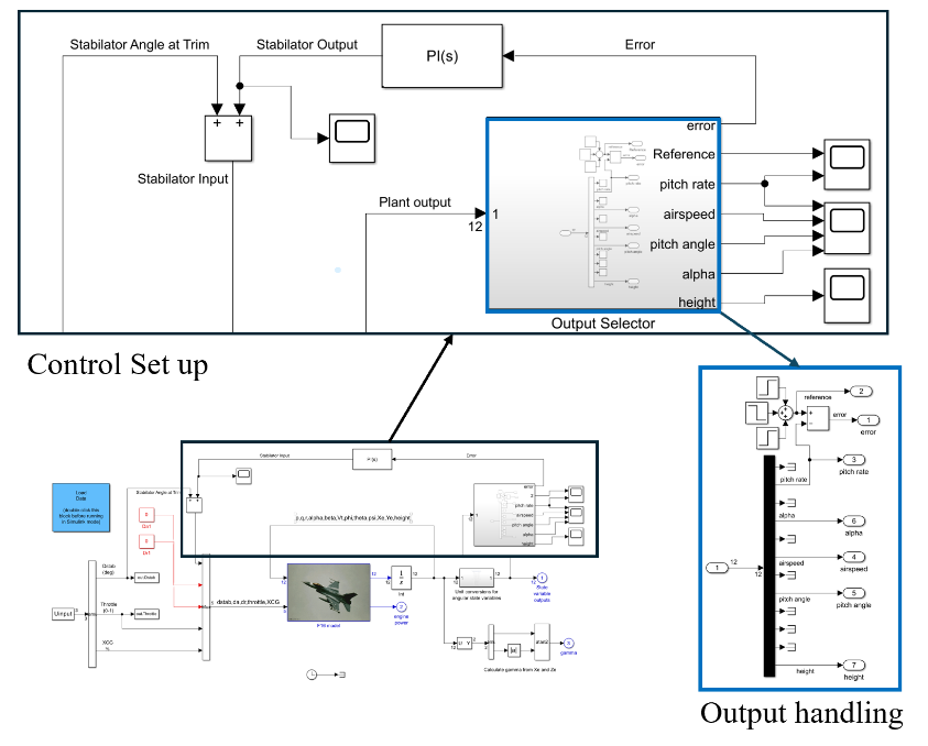
Simulink F-16 model with PI feedback loop and output selection
My PI feedback and output handling around the supplied nonlinear F-16 model. Original report figure, p. 18.

One design point, two speeds

In Simulink, the nonlinear response to a 5°/s command at 220 m/s agreed closely with the linear design, with about 19% overshoot.

At 100 m/s the same gains gave about 51% overshoot in the original coursework run, no clean settling and an angle of attack above 40°. This motivated the airspeed based gain schedule below. The later comparison uses a five second measurement window and gives 44.5% overshoot for the fixed gains; the two figures describe different evaluation windows.

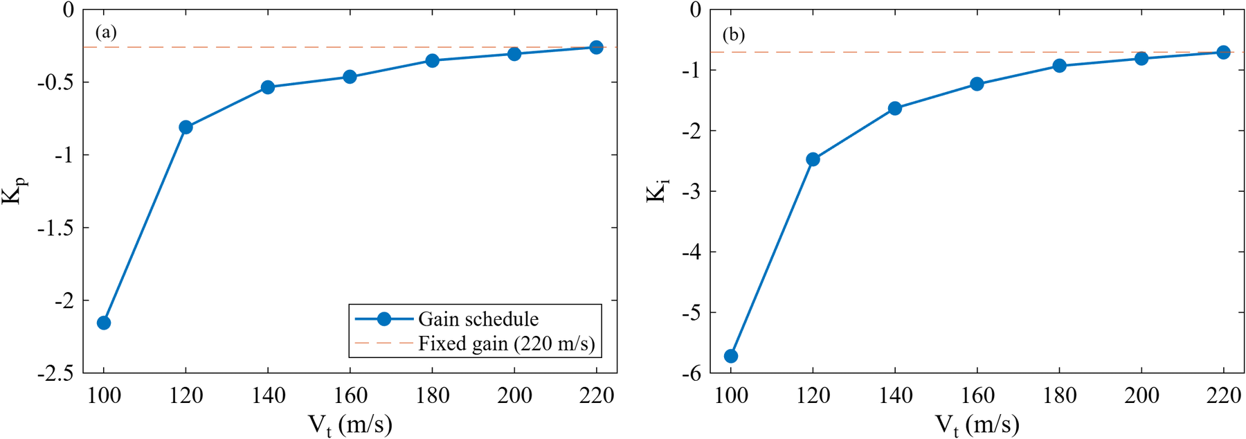
Selected proportional and integral PI gains against airspeed, with the original fixed gains shown for comparison
PI gains selected at seven design speeds. Both gains increase in magnitude as airspeed falls. Gain scheduled controller report, Figure B2.13.

Matching the gains to airspeed

The stabilator loses effectiveness as airspeed falls, so I trimmed and linearised the aircraft at seven speeds from 100 to 220 m/s and repeated the search at each one.

I selected the gains whose response was closest to the original 220 m/s design. Their magnitude rises sharply at low speed; at 100 m/s only four pairs met the criteria.

Two Simulink lookup tables interpolate the gains from measured airspeed and hold the end values outside the range. A switch selects fixed or scheduled control in the same model.

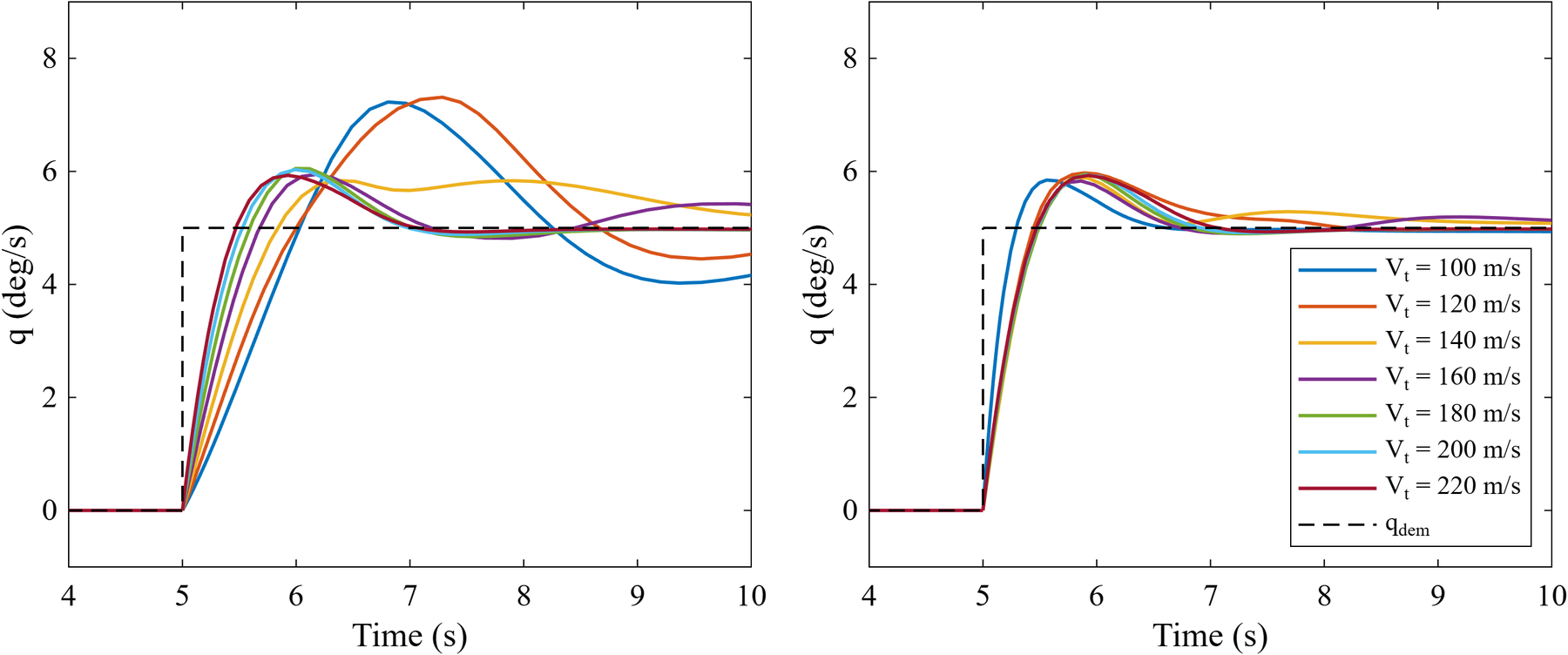
Nonlinear pitch rate step responses at seven initial speeds from 100 to 220 metres per second, with fixed gains on the left and scheduled gains on the right
The same 5°/s command at seven initial speeds: fixed gains (left), scheduled gains (right). Scheduling brings the responses closer together. Figure B2.18.
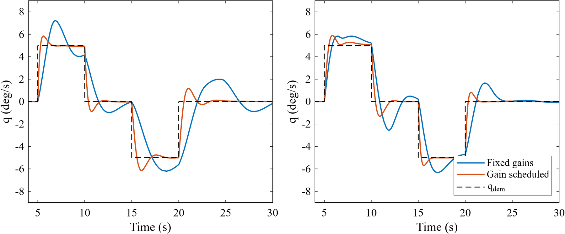
Fixed and scheduled pitch rate responses to positive, zero and negative commands at initial speeds of 100 metres per second on the left and 140 metres per second on the right
Positive, zero and negative commands at 100 m/s (left) and 140 m/s (right). Fixed gains continue to ring after the command changes; scheduling reduces that oscillation. Figure B2.22.

Checking the controller across airspeeds

I tested the nonlinear model at the seven design speeds and six intermediate speeds, using the same trim for each fixed versus scheduled comparison. Commands included a 5°/s step and a positive, zero and negative sequence.

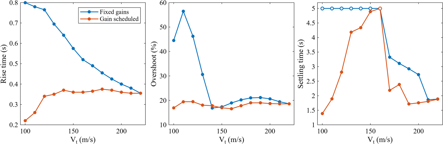
Over the five seconds after the step, scheduling reduced overshoot at 100 m/s from 44.5% to 16.9% and rise time from 0.80 to 0.22 s. At the intermediate 110 m/s point, overshoot fell from 56.5% to 19.4%. All thirteen scheduled cases stayed below 20% overshoot, with rise times of 0.22 to 0.38 s.

Settling was less consistent: the response drifted slowly into the 2% band at 130 to 150 m/s and did not settle within the five second window at 160 m/s.

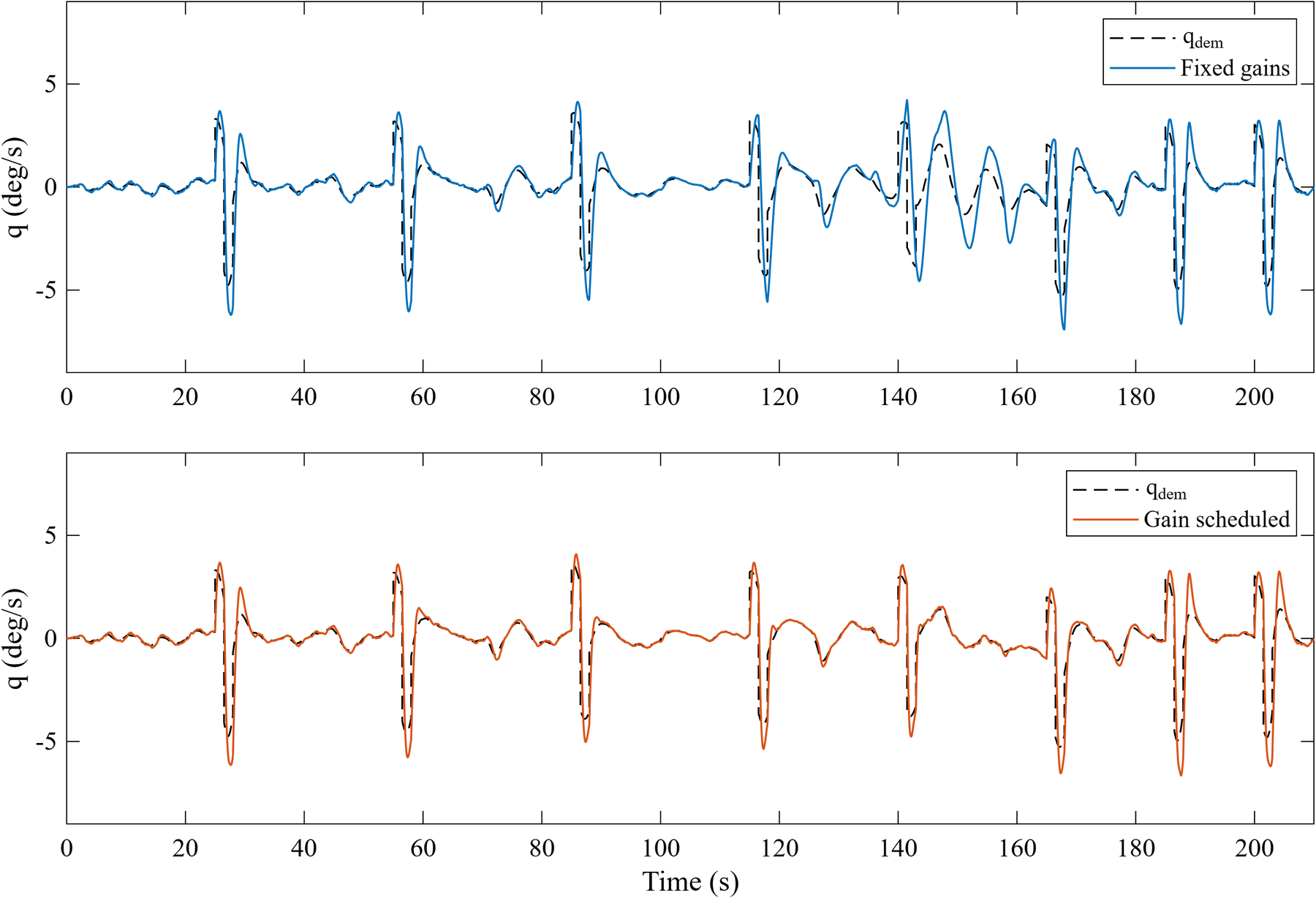
Pitch rate and total demand over the 210 second disturbed flight, with fixed gains above and scheduled gains below
The 210 s flight with gusts and sensor noise: fixed gains above, scheduled gains below. Dashed lines show each run’s pitch rate demand. Figure B2.24.

Testing while the flight condition changes

I built a 210 s nonlinear flight with autothrottle, altitude hold, a 220 to 110 m/s and back speed command, and eight pitch rate doublets. Both controllers ran clean and with three matched seeds of simplified turbulence, gusts and sensor noise, using an ideal stabilator.

Linear designs extended to 80 m/s. However, an 85 m/s speed command let the outer loops take the aircraft to about 55 m/s even without disturbances; all three disturbed scheduled runs lost control. The demonstrated improvement remains around 100 m/s and above.

RMS pitch rate error for fixed and scheduled controllers overall and in three airspeed bands
RMS tracking error, averaged over three runs with matched disturbances. Error bars show the range between seeds. Figure B2.27.

What scheduling changed in the response

Across three disturbed runs, scheduling reduced mean RMS pitch rate error from 1.05 to 0.67°/s overall (36%) and from 1.33 to 0.48°/s below 140 m/s (64%). At high speed the responses were much closer.

Comparing disturbed and undisturbed runs separated disturbance sensitivity from command tracking: the RMS pitch rate change caused by the disturbances fell from about 0.45 to 0.30°/s overall, with close agreement across the seeds.

The cost was greater control activity. Mean RMS stabilator command rate rose from 4.4 to 14.4°/s, with large command steps at low speed. Actuator response is therefore the next integration check.

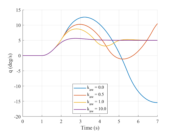
Pitch-rate step responses for four anti-windup gains under a 1 degree per second actuator rate limit
Response with the actuator limited to 1°/s for anti-windup gains of 0 to 10.
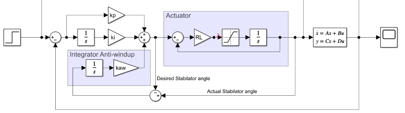
Simulink PI controller with an actuator model and integrator anti-windup feedback
The anti-windup implementation: commanded and actual stabilator angles feed the corrective integral path. Original report figure, p. 21.

When the actuator cannot keep up

On a linearised model, I added stabilator rate limits. At 1°/s the integrator kept accumulating error and the response diverged.

An anti-windup path using the difference between commanded and actual stabilator angle restored a stable response, and command rate limiting also avoided divergence; both slowed the initial response.

The scheduled simulations do not yet include this actuator model, so repeating these tests with the higher low speed gains is the next step.

Step response metrics across the tested speeds

The metrics include all seven design speeds and six intermediate speeds. A hollow settling-time marker means the response did not settle within the five second evaluation window; it does not indicate a measured settling time of five seconds.

Rise time, overshoot and settling time versus initial airspeed for fixed and scheduled PI gains
Nonlinear step metrics at all thirteen initial speeds. Hollow markers identify cases not settled within the five second window. Figure B2.19.

Tools and methods

MATLAB, Simulink, trim and linearisation, modal analysis, numerical gain search, PI gain scheduling, actuator modelling and anti-windup